
The main thrust of our research is to advance the science of low-temperature plasma physics, particularly as applied to semiconductor fabrication. Emphasis has been on the plasma sources used for this purpose: how they work and how they can be improved. These sources run on radiofrequency (RF) power, which makes probing them difficult; hence, considerable work was done on diagnostics, especially Langmuir probes.
Helicon sources have commanded most of our attention because these convert RF energy to plasma density extraordinarily well and may be the source of the future. Unlike other RF sources, these devices work on the principle of wave generation in a plasma. A helicon wave, which propagates in a cylinder along a DC magnetic field, absorbs the RF energy and deposits it efficiently in the plasma. How it does this and why the process is more efficient than others, is a puzzle which took many years to unravel. Helicon research is like an onion: you peel off one layer, only to find another layer underneath that makes you cry. A summary of these layers will follow shortly.
At present the semiconductor industry is not yet ready to adopt helicon sources and is depending on older devices such as the capacitive discharge (or Reactive Ion Etcher, RIE) and the Inductively Coupled Plasma, ICP. Though these reactors are well developed, they are by no means well understood. In particular, the ICP, which requires no DC magnetic field, has an anomalous skin depth. That is, the RF energy penetrates into the plasma and produces a uniform density when it should be stopped within a few centimeters of the surface. Our recent work throws light on this problem. RF sources are a gold mine for interesting physics problems, challenging design problems, and inventive ideas.
Physics of helicon discharges
Click on thumbnails to see full pictures
1. Basic experiments.
Measurements of plasma parameters and wave fields were made in a 160-cm long,
5-cm diam discharge tube in a uniform magnetic field B.  Results
agreed with helicon theory (for nonuniform density profiles) and with classical
diffusion theory, with a few surprises. The density peaked far downstream
instead of near the antenna; the wave field had a beat pattern downstream; the m
= +1 (RH) azimuthal mode dominates over the m = -
1 mode; there is low-B density peak around 50G, etc., etc. All of these effects
have been explained. The main papers of this research are:
Results
agreed with helicon theory (for nonuniform density profiles) and with classical
diffusion theory, with a few surprises. The density peaked far downstream
instead of near the antenna; the wave field had a beat pattern downstream; the m
= +1 (RH) azimuthal mode dominates over the m = -
1 mode; there is low-B density peak around 50G, etc., etc. All of these effects
have been explained. The main papers of this research are:
M. Light and F.F. Chen, Helicon Wave Excitation with Helical Antennas, Phys. Plasmas 2, 1084 (1995).
M. Light, I.D. Sudit, F.F. Chen, and D. Arnush, Axial Propagation of Helicon Waves, Phys. Plasmas 2, 4094.
I.D. Sudit and F.F. Chen, Discharge equilibrium of a helicon plasma, Plasma Sources Sci. Technol. 5, 43 (1996).
F.F. Chen, I.D. Sudit, and M. Light, Downstream physics of the helicon discharge, Plasma Sources Sci. Technol. 5, 173 (1996).
2. Theory. Helicon theory
was extended to treat nonuniform densities analytically. Finite electron mass
was added, resulting in the discovery of helicon coupling to Trivelpiece-Gould
(TG) modes, thus explaining the unusually high RF absorption efficiency of
helicon discharges as well as the dominance of the m = +1 mode. Finally, the helicon discharge problem was reduced to a simple equation, and the
HELIC code was developed to compute wave properties including the effects of
radial gradients, neutral and ion collisions, TG modes, and antenna coupling.
The figure shows that the density gradient makes a big difference;
the dashed curve is for a uniform plasma.
F.F. Chen, M.J. Hsieh, and M. Light, Helicon waves in a nonuniform plasma, Plasma Sources Sci. Technol. 3, 49 (1994).
F.F. Chen and D. Arnush, Generalized theory of helicon waves I: Normal modes, Phys. Plasmas 4, 3411 (1997).
D. Arnush and F.F. Chen, Generalized theory of helicon waves II: Excitation and absorption, Phys. Plasmas 5, 1239 (1998).
D. Arnush, Role of Trivelpiece-Gould Waves in Antenna Helicon Wave Coupling, Phys. Plasmas 7, 3042 (2000).
3. Advanced experiments. The
effect of capacitive coupling was shown in a 10-cm diam device with Faraday
shields and 2D imaging of the discharge:
D.D. Blackwell and F.F. Chen, 2D imaging of a helicon
discharge, Plasma Sources Sci. Technol. 6, 569 (1997).
Capacitive mode. Helicon mode

Azimuthally rotating RF fields with bifilar antennas were
found to be more efficient than simple helical antennas. 
D.G. Miljak and F.F. Chen, Helicon wave excitation with rotating antenna fields, Plasma Sources Sci. Technol. 7, 61 (1998).
A helical wave propagating from a helical antenna
Dual antennas were found to produce
a density minimum, not maximum, at the midplane. This is explained
by gas depletion. 
D.G. Miljak and F.F. Chen, Density limit in helicon discharges, Plasma Sources Sci. Technol. 7, 537 (1998).
Half-wavelength antennas were found
to produce more downstream ionization than full-wavelength ones. This is not yet
understood. 
L. Porte, S.M. Yun, F.F. Chen, and D. Arnush, Superiority of half-wavelength helicon antennas (submitted, 2001).
By developing an energy analyzer with RF frequency response, it was shown that non-Maxwellian electrons were not present in high-density helicon discharges, thus disproving the Landau damping hypothesis.
F.F. Chen and D.D. Blackwell, Upper limit to Landau damping in helicon discharges, Phys. Rev. Lett. 82, 2677 (1999).

 10-cm diam helicon machine
By developing an RF current probe, direct evidence of the existence of TG modes in helicon discharges was found at low magnetic fields.
D.D. Blackwell, T.G. Madziwa, D. Arnush, and F.F. Chen, Evidence for Trivelpiece-Gould modes in a helicon discharge, Phys. Rev. Lett. (2001).
Radial profile of RF current: the "wings" are due to the TG mode. The top curve is theory from the HELIX code.

Large Area Distributed Helicon Source
A source consisting of seven
individual helicon sources successfully produced densities of 1012 cm-3
over a 40-cm diam area with ± 3% uniformity.
F.F. Chen, X. Jiang, and J.D. Evans, Plasma injection with helicon sources, J. Vac. Sci. Technol. A 8, 2108 (2000).
F.F. Chen, X. Jiang, J.D. Evans, G. Tynan, and D. Arnush, Low Field Helicon Discharges, Plasma Phys. Control. Fusion 39, A411 (1997).
F.F. Chen, J.D. Evans, and G.R. Tynan, Design and performance of distributed helicon sources, Plasma Sources Sci. Technol. 10, 236 (2001).
Diagnostics
A large number of diagnostics for use in harsh RF environments have been developed: RF compensated Langmuir probes, radial and axial magnetic probes, local optical probes, CCD camera imaging, RF-resolved gridded analyzer, and RF Rogowski coil current probe.
I.D. Sudit and F.F. Chen, RF compensated probes for high-density discharges, Plasma Sources Sci. Technol. 3, 162 (1994).
F.F. Chen, DC Probe Detection of Phased EEDFs in RF Discharges, Plasma Phys. Control. Fusion 39, 1533 (1997).
F.F. Chen, Langmuir probe analysis for high-density plasmas, Phys. Plasmas 8, 3029 (2001).

Inductively Coupled Plasmas
Classical skin depth theory was
carefully examined and found incapable of  explaining
 the uniform radial density
profiles observed. A Monte-Carlo calculation showed that the nonlinear
Lorentz force can push ionizing electrons into the center of the plasma.
the uniform radial density
profiles observed. A Monte-Carlo calculation showed that the nonlinear
Lorentz force can push ionizing electrons into the center of the plasma.
F.F. Chen, Collisional, magnetic, and nonlinear skin effect in RF plasmas, Phys. Plasmas 8, 3008 (2001).
J.D. Evans and F.F. Chen, Nonlocal power deposition in inductively coupled plasmas, Phys. Rev. Lett. 86, 5502 (2001).
A symmetric ICP experiment. Orbit of an electron in an ICP.
Drift instabilities in helicon discharges
The plasma density in a helicon discharge generally increases with DC magnetic field B, but it saturates at high B. With light gases, it even falls as B increases past a certain point. This was found by Max Light to be caused by the onset of a low frequency instability driven by density gradients and electric field shear.
 M.
Light, F.F. Chen, and P.L. Colestock, Low frequency electrostatic instability
in a helicon plasma, Phys. Plasmas 8, 4675 (2001).
M.
Light, F.F. Chen, and P.L. Colestock, Low frequency electrostatic instability
in a helicon plasma, Phys. Plasmas 8, 4675 (2001).
M. Light, F.F. Chen, and P.L. Colestock, Quiescent and unstable regimes of a

L
Right: Max's machine at Los Alamos.
Plasma processing induced damage
One of the main problems in using plasma to etch high-speed circuits is that
charges tend to build up on the thin gate insulators of the MOSFET
transistors. Huge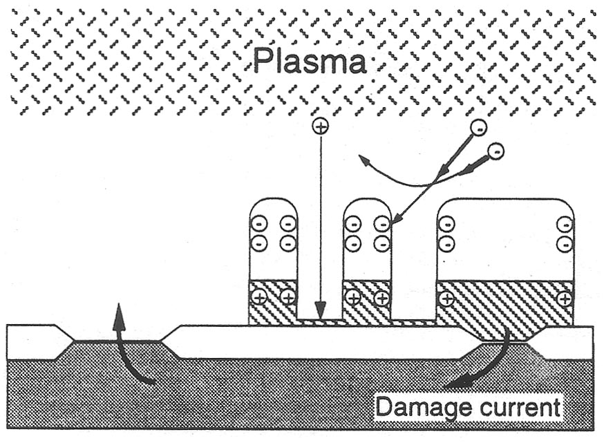 voltages drive currents through the oxide layers to damage them. A widely
accepted mechanism is electron shading damage, in which negative charges
on the photoresist prevent electrons from penetrating into the trenches being
etched, and ions cause positive charge buildup. To test this, we scaled
the experiment so that the trenches are
voltages drive currents through the oxide layers to damage them. A widely
accepted mechanism is electron shading damage, in which negative charges
on the photoresist prevent electrons from penetrating into the trenches being
etched, and ions cause positive charge buildup. To test this, we scaled
the experiment so that the trenches are  of
mm dimensions and could be probed. It was necessary to develop a discharge
with low density and high electron temperature so that the Debye length scaled
accordingly. Modeling of the ion orbits was done iteratively, with each
part of the trench charging to a self-consistent potential. Tsitsi Madziwa
has found that the fields at the entrance control the ion orbits, which are
ballistic inside the trench.
of
mm dimensions and could be probed. It was necessary to develop a discharge
with low density and high electron temperature so that the Debye length scaled
accordingly. Modeling of the ion orbits was done iteratively, with each
part of the trench charging to a self-consistent potential. Tsitsi Madziwa
has found that the fields at the entrance control the ion orbits, which are
ballistic inside the trench.
More figures...
from the laboratory tour following the APS-DPP meeting in November, 2001:
Results from the 5-cm diameter machine (PPT file)
Results from the 10-cm diameter machine (PPT file)
Results from the single- and multi-tube machines (PPT file)
Status of the plasma damage calculation and experiment (PPT file)